

AIR Responder Architecture; overview and performance analysis
What is an AIR responder?
Section titled “What is an AIR responder? ”The AIR Responder is a compact, cross-platform, zero-dependency package that functions as a virtual incident responder, delivering Level 3–4 SOC investigative capability directly to your assets.
Responders interface with the AIR Console to execute precise, user-defined tasks while consuming minimal system resources. This design enables comprehensive investigative coverage without the overhead of continuous telemetry collection or real-time monitoring, improving both cyber resilience and operational efficiency.
The AIR responder maintains regular communication with the AIR Console through several small, purpose-specific HTTPS exchanges. The primary exchange is a lightweight heartbeat poll. It confirms that the responder is online, retrieves pending task assignments, and carries change identifiers for responder configuration and asset state.
Configuration, asset state, and resource metrics are handled separately so the heartbeat does not need to resend all responder and device data on every poll. Task status updates and task results also use their own requests.
Polling interval
Section titled “Polling interval ”Responders send heartbeat polls to the AIR Console at regular intervals. Polling intervals are scaled dynamically for large-scale deployments: the effective interval depends on the organization’s total number of managed assets and whether the console is SaaS or on-premises, using environment-specific defaults, a scaling adjustment above a fixed threshold, and minimum and maximum bounds so polling stays predictable and sustainable. Each responder uses the interval calculated for that combination—no per-asset manual tuning is required as the managed fleet grows or shrinks.
Default polling interval (organizations at or below the scaling threshold use this interval)
- SaaS deployments: 2 minutes
- On-prem deployments: 1 minute
Scaling behavior
When the number of managed assets exceeds 1,000, the polling interval increases from the default according to the formula below. The result is capped so it never falls below the minimum or above the maximum for that environment.
Scaling formula
interval = DEFAULT + (assets - 1000) × 3.33 ms
Where DEFAULT is the base visit interval for the environment:
- 1 minute (on-prem)
- 2 minutes (SaaS)
Bounds
| Environment | Minimum interval | Maximum interval |
|---|---|---|
| On-prem | 1 minute | 10 minutes |
| SaaS | 2 minutes | 20 minutes |
This polling mechanism ensures that responders remain lightweight while still enabling rapid task execution across environments of any scale.
If the responder does not check in at the required interval, it will be shown as offline in the AIR console.
If the responder does not check in for longer than the unreachable threshold of the Stale Asset Policy that owns the asset, the asset is marked as unreachable. The Default policy uses 30 days until it is changed. This status is resolved immediately once the asset is back online, and it does not change the asset’s Managed Status — the asset keeps its responder, so it remains Managed.
Unreachable does not change an asset’s Managed Status. A device with an installed responder stays Managed while it is Unreachable — see Terminology for how Managed, Unmanaged, and Off-Network are defined.
A stale asset policy can later purge the asset record from the AIR console, and optionally uninstall the responder the next time it checks in. Crossing the unreachable threshold on its own neither removes the asset nor changes its Managed Status.
Responder-to-Console communication flow
Section titled “Responder-to-Console communication flow”The modern communication flow is a two-way state synchronization protocol. Each side owns a different part of the shared operating state:
- Console-owned desired state includes the polling interval, connection route, update and security settings, user-agent settings, and optional wake-up channel configuration. The responder pulls this state through the configuration exchange.
- Responder-owned observed state includes responder and MITRE database versions, device and OS identity, hardware capacity, network interfaces, isolation status, and supported capabilities. The responder pushes this state to the Console through the state exchange.
The heartbeat response carries one ETag for each side of this synchronization. The responder compares the Console configuration ETag with the configuration it has already applied, and compares the Console’s stored state ETag with a hash of its current local state. A configuration mismatch causes the responder to pull the latest Console state; a device-state mismatch causes it to push its latest local state. This allows both sides to converge without transferring the complete state on every heartbeat.
Runtime resource metrics are kept separate from this relatively stable state because CPU usage and available storage can change frequently.
| Exchange | Primary data direction | Purpose | When it occurs |
|---|---|---|---|
| Heartbeat | Responder ↔ Console | Confirms availability, updates last-seen information, retrieves pending tasks, and receives configuration and state change identifiers (ETags). | At the calculated polling interval and when an optional wake-up signal requests an early poll. |
| Configuration | Console → Responder | Transfers Console-managed desired state, including the polling interval, connection route, update and security settings, and optional wake-up channel settings. | Only when the configuration ETag returned by the heartbeat differs from the responder’s current value. |
| State | Responder → Console | Reports relatively stable device and responder information, including OS and agent versions, hardware capacity, network interfaces, and supported capabilities. | When the locally calculated state changes or the Console’s state ETag does not match. |
| Metrics | Responder → Console | Reports current CPU usage and available RAM and disk space without resending the complete device state. | The first report is sent after an initial five-minute delay, then every 30 minutes while the modern flow is active. |
| Tasks, status, and results | Console ↔ Responder | Transfers task assignments to the responder, then reports task progress or completion and uploads task output where applicable. | Tasks are returned by heartbeat; status and results use separate requests during and after execution. |
The sequence is as follows:
- The responder initiates an authenticated HTTPS heartbeat, either directly or through its configured relay route.
- The Console validates the responder, updates its last-seen details, resolves pending task assignments, and returns the tasks together with configuration and state ETags.
- The responder compares the returned ETags with its local values. It pulls Console configuration or pushes local device state only when a value is missing or has changed, synchronizing the two sides.
- The responder processes returned tasks and uses separate requests to report status and results.
- Resource metrics continue on their own schedule and are not coupled to every heartbeat.
Optional NATS or AppSync Events connections can reduce task pickup latency. These channels carry only a lightweight wake-up signal that tells the responder to poll early; they do not carry task details, configuration, or results. HTTPS polling remains the source of truth, and normal polling continues if a wake-up channel is disabled or unavailable.
How does the AIR responder work?
Section titled “How does the AIR responder work? ”When the AIR responder receives a task assignment in a heartbeat response, it carries out the task and reports status and results to the AIR Console through the appropriate task APIs. While idle, it continues sending lightweight heartbeat polls and periodic resource metrics. Configuration and full device state are exchanged only when change detection indicates that an update is required.
The AIR responder is capable of executing various tasks when assigned by the AIR Console. These tasks include:
- Acquisition
- Hunt/Triage scanning (YARA, Sigma, osquery, MITRE ATT&CK)
- Isolation
- interACT sessions
- Auto Tagging
- Disk/Volume Imaging
- Investigation (Timeline)
- Baseline
- Log Retrieval
- Certificate Authority Update
- Migration
- Reboot
- Shutdown
- Update
- Uninstall
Both the Acquisition and Disk Image tasks support uploading collected evidence to external repositories, including Amazon S3, Azure Blob Storage, Google Cloud Storage, FTPS, SFTP, and SMB. These tasks enable the AIR responder to securely transfer the acquired evidence or disk images to the designated repositories for storage and further analysis.
By utilizing the supported protocols and repositories, the AIR responder ensures that the collected evidence or disk images are transmitted and stored securely in the designated locations. This enables efficient storage, accessibility, and collaboration, facilitating the management and analysis of acquired data in a secure and scalable manner.
AIR has an option for Windows, macOS, and Linux AIR responders to transmit evidential collections directly to external evidence repositories, thereby efficiently minimizing the utilization of local disk space:
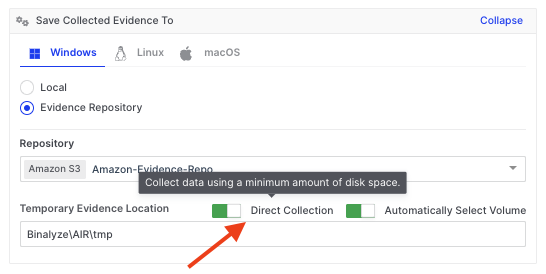
AIR Responder Architecture; overview and performance analysis: Tool Tip explaining Direct Collection for Evidence Repositories
How is the AIR responder secured?
Section titled “How is the AIR responder secured? ”The AIR responder maintains robust security by implementing a range of measures, including:
Encrypted Traffic: The traffic between the AIR responder and the AIR Console, as well as between the AIR responder and any evidence repositories, is encrypted using TLS 1.2 and, if available on the server, TLS 1.3. If neither of these two TLS protocols is available, the connection will not be established. This ensures that data in transit is protected against interception and unauthorized access.
Communication: The AIR responder initiates the authenticated connection to the AIR Console and asks whether task assignments are ready. The Console does not open an inbound connection to the asset to deliver task data. When an optional NATS or AppSync Events channel is enabled, it is also established by the responder and carries only a wake-up signal; the responder then retrieves task details over HTTPS. This outbound communication model reduces the responder’s exposure to external threats.
Privileged Account Usage: On macOS and Linux, the AIR responder uses the root account, while on Windows, it uses the system account. This level of access control makes it difficult for other users to tamper with the application, thereby enhancing its security.
Regular Internal Penetration Testing: Before every release, our internal penetration testing team conducts thorough penetration testing. This proactive approach helps identify and mitigate potential vulnerabilities.
Secure Libraries and Third-Party Applications: We consistently use updated and vulnerability-free libraries and third-party applications. This precaution in maintaining up-to-date software components protects against known security vulnerabilities.
Supply Chain Attack Prevention: Measures are in place to protect against supply chain attacks, and our DevOps team continuously improves these. This is crucial to prevent threats that could compromise the software development and deployment process.
Continuous Source Code Scanning: The source code is regularly scanned by security tools to identify potential vulnerabilities. This constant monitoring enables the quick identification and resolution of any security issues that arise in the codebase.
Digital Signing: The use of digital signatures adds a layer of security, ensuring the authenticity and integrity of our software. This helps prevent tampering and verifies that the software has not been altered after it was signed.
Blackbox Analysis: The binary undergoes Blackbox analysis, a method of testing the software’s external functioning without delving into its internal structure. This type of analysis has been performed on the AIR responder. It helps in identifying security vulnerabilities from an outsider’s perspective, providing a critical view of the system’s external defenses.
Graybox Analysis: For the AIR responder project, Graybox analysis has been conducted. This testing method combines both the internal and external examination of the software, providing a more comprehensive security overview.
Are databases used by the AIR responder?
Section titled “Are databases used by the AIR responder? ”Functioning like a server application, the AIR responder does not use databases. Instead, it operates by saving reports as individual files using SQLite. These reports are subsequently forwarded to the AIR Console. This approach simplifies the data handling process, enabling the efficient and secure storage and transfer of information.
What is the Binalyze AIR design process?
Section titled “What is the Binalyze AIR design process? ”We continuously advance our development process by implementing the SCRUM methodology, complemented by unit and integration testing. The use of both unit and integration testing is crucial for maintaining high-quality standards and ensuring that each component of our product functions seamlessly individually and as part of the whole system.
Resource monitoring for the AIR responder
Section titled “Resource monitoring for the AIR responder ”After the initial installation, it is normal to observe a small amount of memory being allocated, typically around 30MB to 40MB, with no significant CPU or disk usage during idle states. This behavior is expected and can be attributed to the necessary resources required for the AIR responder to function correctly.
During idle states, the AIR responder remains in standby mode, pending its next call to the Console to collect any new tasking assignments. The allocated memory is utilized to maintain the AIR responder’s core functionality and to ensure prompt responsiveness when new tasks are assigned.
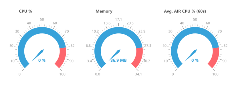
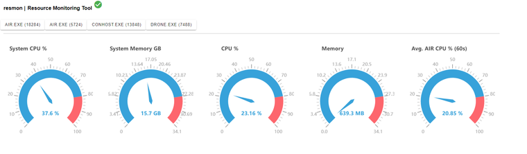
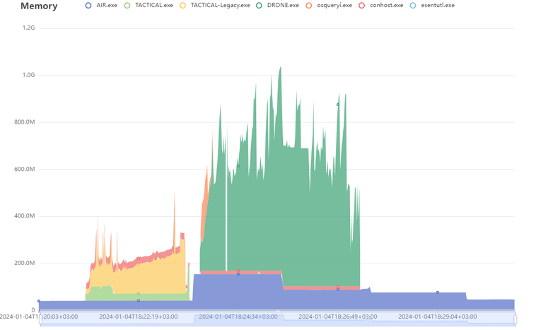
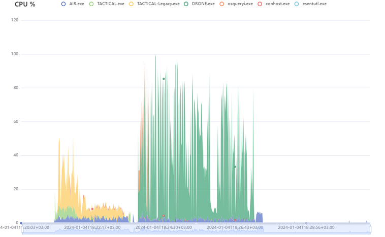
When the AIR responder receives an acquisition task, the evidence collection process is carried out by a subprocess called Tactical (or Incident Response Evidence Collector on Windows). During the acquisition process, it is normal to observe increased CPU and memory usage as the Tactical sub-process actively collects and processes the evidence.
The increase in CPU and memory usage is a result of the intensive data gathering and analysis performed by the Tactical sub-process. It utilizes system resources to capture and process the required evidence efficiently, ensuring the integrity and completeness of the collected data.
The extent of CPU and memory usage during the acquisition task may vary depending on factors such as the size and complexity of the evidence being collected. Once the acquisition is completed, the CPU and memory usage will typically return to normal levels, reflecting the completion of the resource-intensive task.
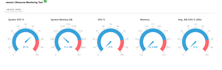
A Hunt/Triage task does not involve running the Tactical sub-process for evidence collection. Instead, the Hunt/Triage task is executed within the AIR responder, utilizing its internal capabilities to analyze and evaluate the collected data.
Although the CPU usage for a Hunt/Triage task is typically low, it is still possible to set a CPU policy for the task.
The log file of the running AIR responder provides valuable information about CPU usage, memory usage, and other system resources. Here is an example of the log entries about system and service resources:
INFO 2024-01-04 18:45:25+03:00 2.31.2 triage: resmon: SysStats{GoHeapAlloc: 2.3 MB, GoHeapSys: 12 MB, NumGoroutines: 27, NumCPU: 16} file:pkg/resmon/handlers.go:16 func:resmon.(*LoggingStatsHandler).HandleSysStatsINFO 2024-01-04 18:45:26+03:00 2.31.2 triage: resmon: PidStats{PID: 9460, Name: AIR.exe, CPU: 14.7%, AvgCPU: 25.9%, Mem: 56 MB, NumFDs: 341, NumCPU: 16} file:pkg/resmon/handlers.go:21 func:resmon.(*LoggingStatsHandler).HandlePidStats
The log file for the AIR responder can be found at the following location:
C:\Program Files (x86)\Binalyze\AIR\agent\AIR.log.txt
You can navigate this path on your system to access the log file and view the relevant information about CPU usage, memory usage, and other resources as logged by the AIR responder during its operation.
Similar scenarios can be observed on macOS with the built-in Activity Monitor application. To access detailed process information, simply click on the (i) button within the Activity Monitor.
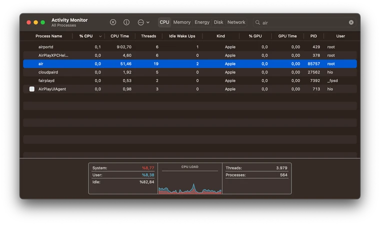
On Linux, an alternative option for resource monitoring is to use htop instead of the built-in app top. The htop option offers enhanced capabilities and can be installed by following these steps:
- Open the terminal.
- Run the command: sudo apt-get install
htop(for Ubuntu/Debian-based distributions) or sudo yum installhtop(for CentOS/Fedora-based distributions). - Once installed, type
htopin the terminal and press Enter to launch the application.
Using htop provides a more comprehensive and user-friendly interface for monitoring system resources on Linux.
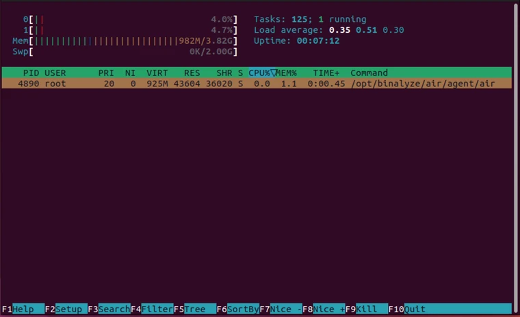
Resource Monitoring with resmon
Section titled “Resource Monitoring with resmon ”There is also a CLI tool named resmon specifically developed for internal usage. It can be used to gather resource usage data related to the AIR responder and its subprocesses, storing them in a local database.
By default, resmon will monitor the AIR responder if no flags are given. However, you can monitor other processes by providing a PID flag or a process name flag. For more detailed information on its usage, a usage document for resmon can be provided upon request.
The information collected by resmon is stored in a local database, which includes numerous entries for the monitored process and its subprocesses. Due to the abundance of entries with comprehensive details, reading and interpreting the data can be a challenging task.
To address this, a script has been developed alongside resmon to visualize these outputs. It displays the CPU and memory usage of the processes (including subprocesses) monitored by resmon in a graphical format.
In the following section, we will share the resmon results as it monitored various task assignments being executed by the AIR responder. Throughout the tasks, resmon will continuously monitor the AIR responder and its subprocesses, generating a comprehensive local database that captures the output of resource monitoring.
For easy visualization, we will utilize a feature of a resmon designed to focus on visualizing its output by presenting the CPU and memory usage in intuitive graphical representations. These visualizations offer valuable insights into the resource utilization of the AIR responder and its subprocesses throughout each tasking assignment, from start to finish.
Analysis of an Acquisition Task
Below, you will find two graphs illustrating the CPU and Memory usage of the AIR responder. These graphs represent the resource utilization from the moment an acquisition task is started through to its completion.
| Duration | Report Size (Zipped) | Database Size | Event Record Count | Drone | Total Disk Space | Used Disk Space | Report Path |
|---|---|---|---|---|---|---|---|
| 06m29s | 199KB | 38KB | 10091 | Enabled | 512 GB | 176 GB | |
Analysis of an Acquisition Task (with CPU limit of 50%)
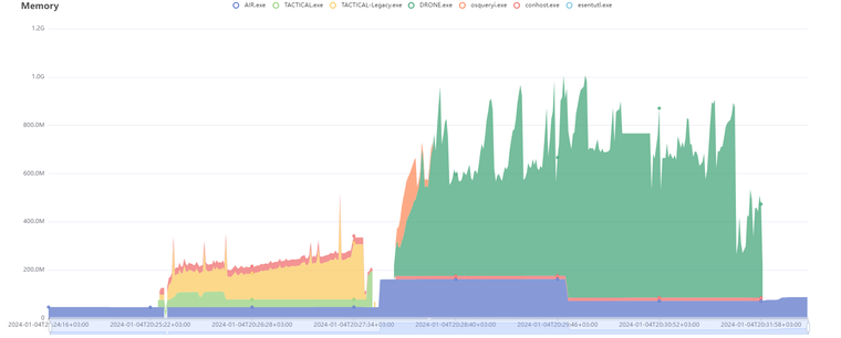
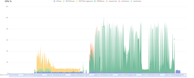
In this scenario, we will examine the CPU and Memory usage of the AIR responder while running tasks received from the AIR Console, with a specific condition: the CPU usage of the AIR responder is limited to 50%.
The visualized graphs provided below depict the resource utilization, explicitly focusing on the CPU and Memory usage of the AIR responder. These graphs illustrate the performance of the AIR responder, highlighting its ability to effectively manage CPU allocation while executing tasks received from the AIR Console.
| Duration | Report Size (Zipped) | Database Size | Event Record Count | Drone | Total Disk Space | Used Disk Space | Report Path |
|---|---|---|---|---|---|---|---|
| 06m48s | 200KB | 39KB | 10102 | Enabled | 512 GB | 176 GB | |
Analysis of a Hunt/Triage Task
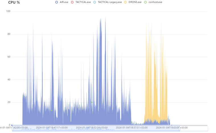
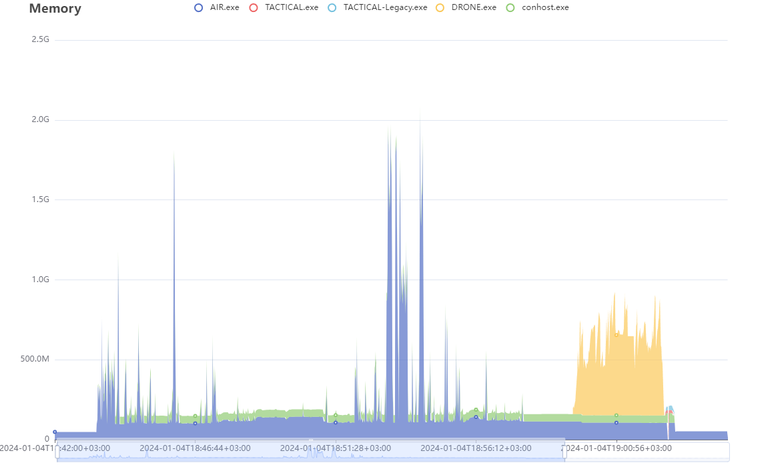
Let’s examine the resource usage of the AIR responder when a Hunt/Triage task is received from the AIR Console.
| Duration | Hunt/Triage Rule Type | Total Disk Space | Used Disk Space | CPU Limit |
|---|---|---|---|---|
| 19m33s | YARA | 512 GB | 176 GB | 100% |
Analysis of a Hunt/Triage Task (with CPU limit of 50%)
Similar to an acquisition task, a Hunt/Triage task can also be configured with a CPU limit for executing the AIR responder. The following graphs illustrate the resource usage of a Hunt/Triage task running with a CPU limit of 50%.
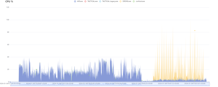
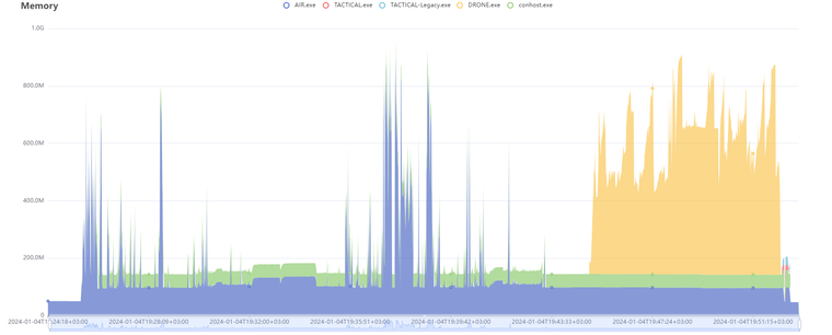
| Duration | Hunt/Triage Rule Type | Total Disk Space | Used Disk Space | CPU Limit |
|---|---|---|---|---|
| 27m09s | YARA | 512 GB | 176 GB | 50% |